Electronic Fundamentals
The interaction between the electrical components of the SRM – High Performance Ergometer allows precise power control for performance diagnostic examination and scientific data acquisition.
The SRM - PowerMeter Science
Reading slope and serial number
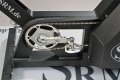
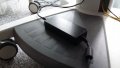
The Power Control IV, abbreviated as PC on the handlebars in the photo
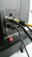
Connecting the Ergometer (Ports)
Connecting the Ergometer (Ports)
|Connecting the Ergometer (Ports)
The PowerControl Ergometer

The PowerControl Ergometer
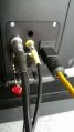
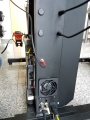
Rear PowerControl Ergometer with one connection
Power supply
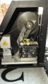
The gearbox

Connecting the Dexlan Ethernet hub
Plug PowerControl

Grounding


.jpg)


Contents
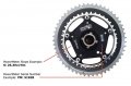
The PowerMeter
The PowerMeter is the central part of the ergometer. It is responsible for measuring the power output. The PM transmits a particular frequency (500 - 12.000 Hz) proportional to the actual torque and also a frequency proportional to the actual angular velocity via a transmitter to a receiver located on the frame. The signal is digital to eliminate transmission errors. Power supply of the PM is by a Lithium battery lasting 1800 hours.
Important: If there is no torque on the chain, the PM does not measure any frequency, which means the angular velocity is zero. Setting this zero offset correctly is important to receive the right measurement of power output.
In the factory we calibrate all SRM PowerMeters in order to determine the frequency change of PowerMeter when changing the torque on the cranks. This frequency is called slope. This slope, measured in Hz/Nm, has to be entered initially into the PowerControl. The slope only has to be reentered if a different PowerMeter is employed, which normally has also a different slope.
The SRM - PowerMeter Science
Reading slope and serial number
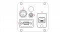
Connecting the Ergometer (Ports)
- Power Supply
- Serial Port
- The serial port is only for the external control by CPX/CPET, EKG or other medical devices by the so called “ergoline” protocol. The idea is to specify the protocols in the CPX/CPET or EKG software to be independend of the SRM Ergometer software.
- Please connect the SRM ergometer via the serial port and the USB-to-Serial Adapter to the controlling computer.
- Please note: If you like to control the protocol by an external device don’t start the performance diagnostics in the SRM ergometer software. The SRM ergometer software are dominant.
- Torque Analysis
- Ethernet Ergometer
Connecting the Ergometer (Ports)
Connecting the Ergometer (Ports)
Connecting the Ergometer (Ports)
Ethernet hub
An Ethernet hub is a network hardware device for connecting multiple Ethernet devices together and making them act as a single network segment. If, for example, a notebook has only 1 Ethernet port this offers a solution. Because if you want to you use both the Ergometer and the Torque Analysis you will need 2 Ethernet ports. It is most likely is does not matter which Ethernut hub you will use but we recommend to take the Dexlan Ethernet hub because is has been tested with the SRM Ergometer.

Front view of the Dexlan Ethernet hub
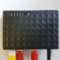
Top view of the Dexlan Ethernet hub
Connecting the Dexlan Ethernet hub


The PowerControl Ergometer
The Power Control Ergometer is the new version of the Power Control and can be used only with the new ergometer control. It receives the HR data displays the measured data, receive the HR data , controlling the eddy current brake and transmitting signals to the computer via a serial cable.
To employ the PowerControl on the Ergometer one has to ensure that the zero offset and slope are correctly entered. All other values such as slope, circumference of tire, etc. are in this case not applicable and has to be changed in the sttings of the ergometer software.
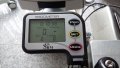
The Power Control IV, abbreviated as PC on the handlebars in the photo
The PowerControl Ergometer
The PowerControl Ergometer
Rear PowerControl Ergometer with one connection
The main menu shows real-time data as the athlete trains.
- Real-time Training Data Menu:
- Top Line: Time - total training time [h:min:sec].
- Middle Line: Power [Watt], Heartrate [bpm].
- Bottom Line: Speed [km/h], Cadence [rpm].
- If no signal from a sensor is picked up, the display shows “-“ for this data instead of a number (for example “Heartrate -“ if heartrate sensor is not paired/connected).
Sensor Pairing
You need to pair the PowerControl Ergometer with the heartrate sensors. If you don’t do this, no heartrate data will be received by the PowerControl Ergometer and can't be saved in the ergometer software.
Please follow these steps:
- Connect the ergometer to the power supply.
- Switch on heartrate sensor by putting the belt on your chest. Please moisten the electrodes to improve contact.
- Switch on the PowerControl by pressing the MODE and PRO buttons simultaneously.
- Select the heratrate sensor you like to pair: Possible heratrate sensors are SUUNTO or the PLUS (the PLUS-SRM heartrate sensor belongs to the ergometer standard accessory)
- Press SET for searching the heratrate sensor; the search bar of the display shows the progress of the search and the antenna symbol is flashing.
- If the geartrate sensor is found, the search bar is completed, the antenna symbol is displayed contineously and in the bottom line the sensor’s serial number is displayed.
- Hold MODE for about 3 seconds to get back in the main display chart, the heartrate should be displayed after a short time.
If no signal is picked up, please check and repeat pairing from the beginning:
- Damp the heartrate belt at the skin sensors to ensure taht the heartrate data can be recorded by the heartrate belt.
- If the sensor is working e.g. with another receiver (e.g. heartrate watch, PC8).
- Check the battery of the hartrate sensor.
- If it is still not working, please get in touch with the SRM Service Center.
Control test with PowerControl keys
You have the possibility to start and stop the test (or the training session) with the keys of the PowerControl.
- Keybord Shortcuts
- PRO (short): Test Start
- SET (short): Test Pause
- PRO (long): Test Resume
- SET (long): Test Stop
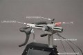
The Power Supply
The power supply has been especially designed to suit the SRM Performance Ergometer. The power supply changes the magnetic field in the eddy current brake very rapidly to ensure a constant rotational speed in isokinetic mode. In the isokinetic mode it is necessary to reduce the braking power to near zero when the cranks are in vertical position. In horizontal position the braking power has to be up to 4000 watts. This is necessary to maintain the predetermined rotational pedaling speed. This means that at a cadence of 120 rotations per minute the magnetic field in the brake has to be established and abolished four times per second.
The power supply operates with 220 Volts, and incorporates fuses of 1.3 A. The power point which is used for the power supply has to be well earthed (grounded) in order to avoid that the athletes become electrostatically charged. WARNING: Operation of the ergometer through an unsatisfactorily earthed power point can damage the health of the athlete and the physiologist and can also lead to wrong ECG readings.
The operating mode of the power supply is indicated by a green LED display. The yellow LED display indicates the operation of the brake. The yellow LED has to flash during isokinetic mode.
Place the power supply in dry, well aired condition. Avoid switching the power supply on and off in quick succession. Never clean the power supply with water or other fluids, the electronics will be damaged.
The current transmitted by the power supply is +/- 24 Volt. The power supply charges the PowerControl unit. If the PowerControl is not charged over a period of about 3 months, it may lose the programmed operating parameters. In this case the user has to charge up the PC via the dedicated charger and enter all operating parameters again with the software SRMWIN.
The power supply does usually not need any maintenance. Wipe with a dry cloth and be sure that no moisture gets into it.
Light Barrier
The light barrier measures the speed of the fly masses. She is a necessity for the power measurement. If speed is not measured correctly, the power measurement is not correct either. The displayed speed values in the SRMWin-Software - e.g. during a performance test – do not correspond to real speed values.
Adjustments
It is possible to do some adjustments to the SRM Ergometer if it is necessary.
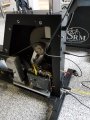
Relocating Plug
The cable of the PowerControl could be too short with the new SRM Ergometers. This occurs by pulling up the steering wheel of the Ergometer. In order to solve this the plug of the PowerControl will be relocated.
Front view relocating plug PowerControl
Side view relocating plug PowerControl

Grounding
Not every SRM Ergometer has been grounded thoroughly for international standards. This could be fixed easily by adding some more grounding like in the images below.

Front view grounding
Side view grounding
