SRM-Online represented practically
|
Languages |
|---|
Contents
Introduction
In the following sections, you can see prepared the ergometer and programmed protocols to perform several performance tests.
General preparation for performance diagnostics
- Power-on spiroergometry (30min before beginning of test)
- Power-on ergometer’s power supply
- Preparation diagnostic devices (Lactate analysis, etc.) 30min beginning of test
- Room temperature (18 – 24°C) should measured
- Relative air humidity should measure (30 – 60%) in room
- Check position of ventilator
Athletes


- Welcoming
- Clients prepare for test - put on the heart rate strap
- Choose the option “Add new athlete” to create a new profile or “Search” for an athlete you added before
- Documentation of personal data of client (name, height, weight, gender, date of birth, crank length)
- Completion questionnaire / exclusion of liability
- Discussion of the data and test procedure
Ergometer preparation for testing & training
Before every performance diagnostic or every training you should check the positioning of the athlete. The mechanical adjustment of the SRM – Ergometer allows the rider to find his individual positioning.
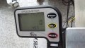
Settings the Crank length


First we recommend to mount the client’s pedals and set-up the crank length as on client’s bicycle.
The prolongable crank has round markings every 2.5 mm and every 10 mm a line. If the steel element of the crank is completely retracted in the aluminium crank the minimal length of the crank arm is 150 mm. If the crank arm is completely pulled out, the maximal length is 190 mm. Before changing the crank arm length you have to open both Allen screws.
After adjusting the right crank arm length, please tighten the Allen screws again with a maximal torque of 10 Nm so that they won’t come loose while you ride the Ergometer. Make also sure that the screws are situated with a distance of a 2.5 mm. This can be determined when the fixing spring (situated between the Allen screws) locks into the holes of the steel element of the crank. Please do never remove or adjust the fixing spring.
From time to time it is necessary to grease the steel elements of the crank to protect them from sweat and to maintain the free movement.
Mechanical adjustment & positioning of the athlete
Optimizing individual positioning is quickly achieved by adjusting the saddle and handlebar vertically and/or horizontally. To do so you have to open the locking lever. Because of a ruler which is attached to the saddle post you can reproduce your perfect positioning. If adjusted correctly, it should be easy to move the vertical and horizontal stems when the quick release is open. A 5 mm Allen key situated on the saddle and handlebar mounts allows for further rigidity.
Horizontal & Vertical Positioning of the saddle


The ruler which is integrated in the seat stay gives you the distance between the center of the bottom bracket and the front of the saddle. The distance in cm can be read from the left hand side of the seat stay.
Fly masses
The mass moment of inertia of a cycling athlete causes an approximate constant angular velocity of the pedaling circle, although thee cyclist´s torque (power) is nearly zero when the cranks are in vertical position. If the SRM Ergometer had no fly mass, the cadence would decrease to nearly zero in the vertical crank position and high power output, resulting in a non-circular pedal cadence. This would result in a very non-circular tread then. Therefore the SRM Ergometer is currently equipped with two fly masses: SMALL (12mm thick, 4,6kg) and LARGE (24mm thick, 9,1kg).
Notice
The default configuration for the most common Ergometer tests is installing the LARGE fly mass inside the gearbox on its own! Please remove the SMALL fly mass as described below! For more information on kinetic energy simulation, fly masses and gear ratio of the Rohloff hub see the manual or visit our webpage at www.srm.de
Removal and mounting instructions

Always disconnect thee power supply from the Ergometer when opening the side covers! Never operate the Ergometer without the side covers! Before removing side covers insure fly masses have stopped spinning completely and use care when handling the fly masses to prevent injuries or bruises – both are very heavy!
- To remove/mount a fly mass you need the following tools: One or two aluminum spacer, Torx screwdriver an nut wrench (Fig.1)
- Open the cap of the Ergometer by removing the seven Torx screws (marked red) with the Torx T30 wrench (Fig.2)
- Use the nut wrench to rotate the brass nut counterclockwise (Fig.3). Hold the fly mass to counter the tool pressure if needed
- Remove the nut and pull the two fly masses off thee axle (Fig.4). Pay attention not to damage the threads on the axle
- Replace the SMALL fly mass with one aluminum spacer (Fig.5) or add two spacers when replacing the LARGE fly mass. Make sure the groove :in the spacer coincides with the feather key in the axle
Always insure the correct fly mass/spacer configuration: When installing both fly masses always add the SMALL fly mass first onto the axle. When removing the SMALL fly mass, add one spacer first, then add the LARGE flywheel. Same when replacing the LARGE fly mass – add the SMALL fly mass first and then add the two spacers. When testing without any fly mass remove all parts including the brass nut.
- To reinstall the fly mass on the axle (Fig.6) make sure the groove in the fly mass coincides with the feather key in the axle. This :groove will lock the fly mass an prevent thee fly mass from spinning free
- Using the nut wrench, rotate the brass nut clockwise until hand-tight (Fig.7)
- Make sure the fly mass sits firmly, has no play on the axle and can rotate freely! Remove all tools inside the gearbox! Reinstall thee :cover with the seven Torx head screws. Do not over tighten!
See also: Gearbox and fly masses functions
Bike fitting


Transfer settings of client’s own bike to the sitting position.
Saddle height
The heel with the extended leg should reach the lowest position in the pedaling cycle.
Saddle setback
In the horizontal position of the crank the knee (patella) should be perpendicular to the pedals axle.
Rohloff gear check

We recommend to verify the gear of thee Rohloff hub before every test or training. Our general recommendation is to use gear 9 - corresponding to the red point at the turning handle.
Preparation of the PowerControl Ergometer
Zero offset calibration
PC Ergometer
- The zero offset calibration has to be done before every new assembly of the PowerMeter and also before every measurement resp. every training on the Ergometer. A wrong zero offset calibration can result in an internal miscalculation of the power.
- Please perform the zero offset calibration as it is described below:
- *For a manual comparison, please turn the right unloaded crank clockwise to activate the PowerMeter.
- *By simultaneously pressing MODE and SET, the PowerControl turns into calibration mode.
- *Wait a few seconds until the value on the right-hand side of the display stabilized itself.
- *Press SET to apply the zero offset.
- *The number on the right-hand side of the display is the current frequency of the PowerMeter (SET).
- *The number on the left-hand side of the display is the frequency which is used for the power measurement (MANU).
- == Warm-up ==
- *Recommendation of at least 3 - 4 min with a low workload (e.g. 75-100W)
- **predefined warm-up
- *Check the correct settings for:
- **Heart rate
- **Cadence
- **Power
- **Speed
- == Workouts ==
- Determine the test protocol:
- *Add new workout
- *Import new workout
- *Drop file to import workout
- You can import new workouts as .erg files and as .fit files.
- == Test ==
- === Start and Stop performance diagnostics ===
- '''BRAKE OFF:''' The brake is deactivate and the client can continue pedaling without resistance and cool down – continuous recording of the heart rate
- === Next steps ===
- *Comment: Entry file name then press Save
- *Recommended cool – down - protocol with lower workload
- *Clean the ergometer (!)
- == Activities ==
- *Select activity to analyze, export or delete
- *Export activity as .fit file, pdf, png, jpg
- *Activity-ID is automatically generated
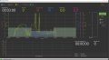
- == Hyperbolic Performance Test (incremental stress test) ==
- *The current power is shown green colored
- *The current heartrate is shown red colored
- *The current cadence is shown blue colored
- *The current speed is shown pink colored
- *The current heart rate value is represented with a red line on the lower part of the monitor image. The power is represented by a green line and the cadence by a blue one.
- *The graphic scaling adjusts automatically to the produced power.
- * Under ''Total Time'' you can see the ridden time so far
- * Under ''Countdown next step'' you can see the remaining time until proceeding to the next step
- *The colored bars in the upper right area have the following function:
- At 90 to 100 % completion of the cadence guideline, the bar stays green. At 80 to 90 % completion the bar turns yellow and at 70 to 80 % it turns red. There is no display of larger deviations.
- The intermediate status display has the following functions:
- *''No Brake'' or ''Brake on'' works only in combination with an Ergometer.
- *By clicking on ''Prev. Step'' / ''Next Step'' you can, depending on what you have adjusted at the ''Predefined File'' level, go back to the previous step / marker or jump forward to the next step / marker.
- *By clicking of ''Set Marker'', you can place markers during the test.
- *''Stop Ergo'' works only in connection with the Ergometer and if there will be no cadence.
- *You can end the test and leave the online program by clicking on ''Exit'' / ''End''.
- You can increase or decrease the current guideline (power, heart rate, cadence) for the test via the arrow buttons (up / down).
- == Isokinetic Performance Test ==
- * The first grey block corresponds with the first planned power output of 100 watts
- * The second blue block shows a targeted cadence of over 90 rpm
- * The third red block equals the previously set heart rate guideline of 130 bpm
- == A combination of the Hyperbolic and the Isokinetic Performance Test ==
A combination of the Hyperbolic and the Isokinetic Performance Test

