Torque Analysis - Tretkraftanalyse
|
Languages |
|---|
Die SRM Ethernet Torque Analyse Hard- und Software wurde entwickelt, um die Pedalkraft des Benutzers in Echtzeit darzustellen. Weiterhin besteht die Möglichkeit die Daten aufzuzeichnen und zu analysieren.
Torque Daten helfen dabei die optimale Rad Anpassung zu bestimmen. Des Weiteren können sie veränderte Sitzpositionen auf ihre Effektivität hin überprüfen und die Radfahrdynamik des Athleten bestimmen. Immer größere Bedeutung erfährt die Torque Analyse im Feld der Rehabilitation nach Verletzungen der unteren Extremitäten. Die gesammelten Daten können gespeichert, neu geladen und exportiert warden, so dass sie in verschiedenen anderen Anwendungen und Formaten benutzt werden können.
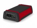
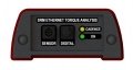
Frontansicht Torque Box
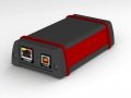
Rückansicht Torque Box
Frontansicht Torque Box
Rückansicht Torque Box
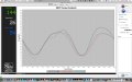
Hauptgrafik der Tretkraftanalyse
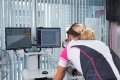
SRM - Software: Kontrolle der Tretkraftanalyse
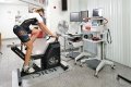
Die Tretkraftanalyse während einer Leistungsdiagnostik


Anforderungen
- SRM Ethernet Torque Box
- SRM Powermeter mit einer integrierten Spule und einem Sensor Kabel
- Computer der mit entweder: MS Windows XP, Vista oder 7; Mac OSX 10.5 oder höher; Linux Kernel 2.6 oder höher läuft
- Installiertes Java Interpretierprogramm auf dem Computer
- Ethernet Verbindung und Cat5 Patchkabel
System Einstellungen
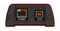
Anschlüsse u. Verbindungen
Die SRM Torque Box wird folgendermaßen verbunden:
- Sensor: Analoges Sensor Kabel
- Ethernet: LAN Verbindung
- Digital: Reserviert für zukünftige Verwendungen
- + 5v DC: Netzteil
- Cadence: Zeigt eine Umdrehung an
- On: Zeigt an ob das Gerät angeschaltet ist
Anmerkung: Die Energie Versorgung durch einen USB-Anschluss an einem Computer reicht nicht aus um die SRM Ethernet Torque Box laufen zu lassen. Bitte benutzen Sie das externe Netzteil.
Frontansicht Torque Box
Rückansicht Torque Box
Software Installation
- Laden Sie die neueste Version der SRM Torque Software von www.srm.de runter
- Installieren Sie die Software. Falls benötigt, wird Java automatisch heruntergeladen und auf ihrem Computer installiert
Hardware Installation
- Überprüfe die PowerMeter Installation und das Sensor Kabel
- Verbinde die SRM Ethernet Torque Box mit dem Sensor Kabel indem du die analoge Schnittstelle der SRM Ethernet Torque Box benutzt
- Verbinde das AC Netzteil mit dem Power Anschluss an der SRM Ethernet Torque Analyse Box; überprüfe ob das LED für Power an ist und grün leuchtet (Falls es Probleme gibt gehe weiter zu Troubleshooting)
- Sichere die SRM Ethernet Torque Box in einer stabilen Position
- Beginne mit dem Radfahren an und überprüfe ob das Cadence LED einmal pro Umdrehung bernsteinfarben aufleuchtet
- Verbinde das Netzwerkkabel mit dem LAN Anschluß an der SRM Ethernet Torque Analyse Box und mit dem Computer
Netzwerk Einstellungen

- Kontrollieren Sie die SRM Ethernet Torque Box Standard IP Adresse auf der Unterseite der Hülle. Die letzte Ziffer der IP Adresse ihres Computers (siehe nächster Schritt) muss von der der Torque Box abweichen
- Wählen Sie eine freie und gültige IP Adresse für Ihren Computer im gleichen Teilnetz wie die SRM Ethernet Torque Box (192.168.0.x)
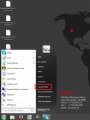
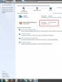
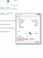
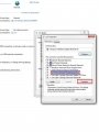
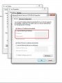
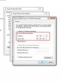
- Falls Sie MS Windows benutzen: Drücken Sie den „Start” Knopf, öffnen Sie „Control Panel”, öffnen Sie „Network and Internet”, wählen Sie „Network and Sharing Center” aus, klicken Sie auf „View Network Connections”, klicken Sie auf die Verbindung die Sie ändern müssen (d.h. LAN), öffnen Sie „Properties”, Doppelklick auf „Internet Protocol Version 4 (TCP / IPV4)” und setzen Sie die ausgewählte IP Adresse ein.
- Geben Sie bitte eine andere IP Adresse als die der Torque Box ein. Ändern Sie dazu nur die letzte oder die letzten zwei Zahlen der Torque Box IP (z.B. 192.168.0.89). Ansonsten kann es Konflikte mit den IP Adressen geben.
Systemsteuerung
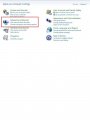
Netzwerk und Internet
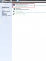
Netzwerk- und Freigabecenter
Öffnen Sie die Netzwerk Verbindung
Eigenschaften
Internetprotokoll Version 4 (TCP/IPv4)
Folgende IP-Adresse verwenden
IP-Adresse: 192.168.0.89


- Falls Sie Apple OSX benutzen: Starten Sie „System Preferences“ im Apple Menü (oder Spotlight), klicken Sie das „Network“ Symbol unten rechts, klicken Sie auf den „Advanced“ Knopf, wählen Sie „Manually“ im Pulldown Menü neben „Configure IPv4” und geben Sie die ausgewählte IP Adresse ein.
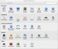
System Preferences
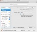
Network
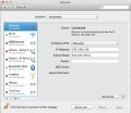
Set the IP Address under Ethernet


Software setup
- Launch the SRM Torque Software
- When the software first runs, a writable folder needs to be defined to save the data. Select a folder.
- Main screen is now shown; go to Settings by clicking on the lower right corner button or through the Options-Settings on the top menu and configure the program
Start pedaling, and check the connection indicator on the lower left corner of the screen: this indicator should be green, if not go to log tab and check the messages. Program settings and log file will be stored under the user's document folder:
Win XP: C:\Document and Settings\Document\SRMTrainingSystem\SRMTorque
Win Vista/7: C:\Users\Document\SRM TrainingSystem\SRMTorque
OSX: /User/Documents/SRM Training System/SRMTorque
Screens
Main screen
The majority of this screen is taken by a graph showing online data:
- the x-axis of this graph is measuring the angle of revolution in degrees
- the y-axis represents the torque in Newtonmeters.
The right side of this screen has two buttons: Record /Stop and Reset Pressing the Record button begins recording, pressing the Reset button clears all stored data. Here you can define the „Automatic stop“ settings. Selecting „None“ will result in recording revolutions until stopped manually.
Selecting „Revolutions“ will result in recording the specified number of revolutions entered. Selecting „Time“ will result in recording the specified seconds of time entered.
The „Notes“ area is for entering information specific to the revolution data that you record; any notes entered here will be displayed in the revolution table in the „Analysis“ view.
Directly below the main graph, there is a field showing numerically the index of the revolution with the relative cadence and power.
The bottom of the main view has a tracking feature which allows you to see specific angle and torque data as you mouse over the graph.
Analysis screen
The top part of this view contains a revolution table, showing data from all recorded revolutions with the appropriate graph for the selected revolutions underneath.
Zoom with the mouse. Hold the left mouse button and open a zoom window or turn the mouse wheel to zoom in/out. Click and hold the left mouse button and wipe left/right to zoom out. The right graph can be set to show two different torque graphs: „Overlapped“ and „Rounded“: „Overlapped“ displays torque data split into two series: from 0 to 179 and from 180 to 359 degrees.
„Rounded“ displays torque data split into 2 inverted series to better visualize roundness of complete revolution.
Note: Moving the mouse cursor over the revolution line in the graph will popup a message that shows the degrees of the relative series. Selecting multiple revolutions results in the graphical display of all revolutions (For windows operating system, this is done by pressing Ctrl-Click. When using Mac OS, this is done by pressing Command-Click).
The right side of this view has an „Export - Save and Load“ area; to export data, first select the desired revolutions.
Then select the output format (CSV, PNG, or PDF) and choose what type of graph(s) you need. Pressing the „Export“ button will export all selected revolutions.
CSV File syntax (for each exported revolution): ROW 1: Header: Index, Cadence, Power, Torque, Slope, Zero, Delay, CrankLenght, Weight, ROW 2 ... N: Body: Angle [Deg], Value [Hz]
To calculate the average graph of revolutions select two or more revolutions. Press the „Calculate Average“ button in „Data Operation“ area.
The „Save“ button allows you to save all checked revolutions (marked with the „Save“ column in revolution table); the number of revolutions is shown
on the „Save“ button.
All files will be saved in the data folder defined in the „Settings-System“ window.
The naming of the SRM Torque Analysis file (.sta) is:
„initials-YYYY.MM.DD HH.mm.SS.sta“
where „initials“ will represent the system's user name.
The „Load“ button allows you to open revolutions previously saved; press the „Load“ button, select a file, then press „Load File“ button (uncheck
„Update Statistics“ if you do not want the file to affect current statistics). Pressing „Select File“ allows you to Load another file; when all files are loaded, press „Close“ to exit the window.
The „Marker operation“ area is used to delete and colorize markers. First, select one or more revolutions, then click a starting point, followed by an ending point. The delta of these two points will be displayed in the lower left corner of the graph, showing both „Angle“ in degrees and „Torque“ in Nm.
Statistics screen
The upper half of this view contains two histograms that show the Cadence and Power distribution for all recorded revolutions.
The lower half of this view contains a scattergraph that shows the relationship between Cadence and Power for all recorded revolutions
Log screen
The Log view contains a complete listing of all relevent events that occured in the software during the current session:
- Connection information
- Save messages
- Load messages
- Device status
- Error notifications
- Recording events
Settings
The Settings window has 5 tabs. The „Graph“ tab allows you to change the number of simultaneous revolutions shown on the main graph, as well as select custom colors for each revolution by clicking on the color. The „Add“ and „Delete“ new revolution buttons allow you to change the number of revolutions shown between 1 and 10. Checking the „Automatic torque scale“ box will result in a self-adjusting y-axis for torque values. By leaving this box unchecked, you can manually select the maximum torque value shown on the y-axis of the main graph.
The „User“ tab contains the user information. The profile drop-down box contains a list of all available users with their information shown when selected.
To change any parameters to a user, select the appropiate user, insert the new value and click „Apply modification“ button. To delete a user, select user and press „Delete User“ button. To create a new user, input a user name for the profile, all the information, then click „Add User“ button. The current user profile is shown in red. To change the user, select a different user from the „User profile“ drop-down box, and click „Set Default User“ button; the current user information will be updated.
The most important information for a selected user profile as name, weight and crank length are shown in the statusbar on the bottom of the window when it gets updated.
The „PowerMeter“ tab is needed to change PowerMeter's parameters: the zero offset value and the slope of the PowerMeter as well to define where the revolution starts. The „Network“ tab allows to change all network settings like IP address and port.
The „System“ tab shows all network interfaces on your computer and is important when configuring your network address. Also, the destination folder for stored data can be changed here.
Utilities
Simulator
The simulator is a part of the SRM Torque Analysis software that allows simulation of revolutions; to enable this go to „Utilities - Simulator“ menu and
then press start.
Make sure to select „Simulator“ also in the „Network profile“ on the settings menu.
Cadence Bell
This option will enable a cadence signal for each revolution when the signal is triggered.
Troubleshooting
General
- Power LED doesn't switch on
- Check the power supply and the power cable connection
- Cadence LED doesn't flash for each revolution
- Check the position of the sensor: the correct position is a tangental point to the coil of the PowerMeter, at a perpendicular angle. Normally, this is a point 5cm from the center of the PowerMeter axle. Move or rotate the cable while pedaling until Cadence LED flashes.
- Power / Torque values shown on „Main“ screen are not accurate
- Ensure the PowerMeter settings are correct: check the slope and the zero offset values on Settings-Powermeter window
- No connection between the PC and the SRM Ethernet Torque Box
- Check the network configuration on your computer, ensure the IP address is the same subnetwork of SRM Ethernet Torque Analysis box
- SRM Ethernet Torque Box's IP adress lost
- Use the DeviceInstaller Utility to find and setup a new IP adress
- The revolution graph is not in the right position
- Check the relative parameter on „PowerMeter profile“ considering the activation point
- Position of the sensor cable
- Check position of sensor cable to ensure it is passing over the cadence switch at a distance in between 3 and 5 mm.
- Powermeter - no signal
- If the position of the sesnor cable is okay and still no signal of the PowerMeter is received, the battery might be the reason. The battery is not self-replaceable. You will need to send the PowerMeter for SRM for replacement. Battery life of the PowerMeter varies between PowerMeter models (700-1900 hours of use). If the variance of your zero-offset frequency is higher than normal and your hours of usage is in the range above 700 hours, your battery likely needs to be replaced.