Mechanical Fundamentals
|
Languages |
|---|
The mechanical adjustment of the SRM – Ergometer allows the rider to find his individual positioning.
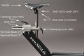
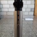
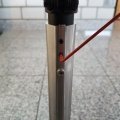
Designations seatpost and rulers
Designations handlebars and rulers
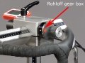
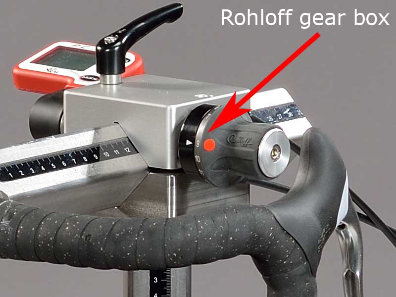
Rohloff Gear Box
Prolongable Crank 1
Prolongable Crank 2
Change of the flyingwheels
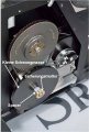
Illustration with smaller flywheel and corresponding spacers
Flying masses


Contents
Positioning of the athlete
Before every performance diagnostic you have to check the positioning of the athlete.
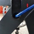
Optimizing individual positioning is quickly achieved by adjusting the saddle and handlebar vertically and/or horizontally. To do so you have to open the locking lever. Because of a ruler which is attached to the saddle post you can reproduce your perfect positioning.
If adjusted correctly, it should be easy to move the vertical and horizontal stems when the quick release is open. A 5 mm Allen key situated on the saddle and handlebar mounts allows for further rigidity.
- Horizontal Positioning of the saddle
- The ruler which is integrated in the seat stay gives you the distance between the center of the bottom bracket and the front of the saddle. The distance in cm can be read from the left hand side of the seat stay.
- Sobald die Position des Sattels auf der Sattelstütze verändert wird passen allerdings die Abstände mit den den eingeklebeten Linealen nicht mehr überein. Dann müssen die Abstände auf den Linealen manuell korrigiert werden oder evtl. neue Lineale eingeklebt werden.
- Vertical Positioning of the saddle
- Horizontal Positioning of the handlebars
- Vertical Positioning of the handlebars
Designations seatpost and rulers
Designations handlebars and rulers
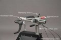
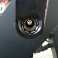
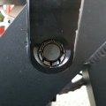
- Prolongable Crank
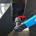
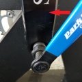
- The prolongable crank has round markings every 2.5 mm and every 10 mm a line. If the steel element of the crank is completely retracted in the aluminium crank the minimal length of the crank arm is 150 mm. If the crank arm is completely pulled out, the maximal length is 190 mm. Before changing the crank arm length you have to open both Allen screws.
- After adjusting the right crank arm length, please tighten the Allen screws again with a maximal torque of 10 Nm so that they won’t come loose while you ride the Ergometer. Make also sure that the screws are situated with a distance of a 2.5 mm. This can be determined when the fixing spring (situated between the Allen screws) locks into the holes of the steel element of the crank. Please do never remove or adjust the fixing spring.
- From time to time it is necessary to grease the steel elements of the crank to protect them from sweat and to maintain the free movement.
Prolongable Crank 1
Prolongable Crank 2
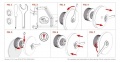
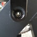
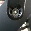
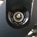
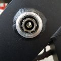
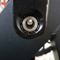
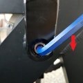
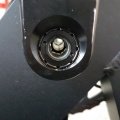
Removing saddle
The SRM ergometer includes a standard saddle. A lot of professional cyclists have there own specialized saddle. So it is important to be able to remove the saddle. The following images show how it is done.

SRM saddle
Screws saddle
Allen key for removing
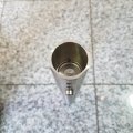
Pipe without saddle


With the removal of the two upper screws you will be able to remove the saddle. The bottom screw provides a platform within the pipe of the saddle. This platform keeps the saddle right at the top, so there aren't any problems with the adjustments of the saddle during bike fitting.
Removing cranks


By following these 12 steps you will be able to remove the cranks of the ergometer. The three images on the right provide an overview of the used materials.
- 1. The first two images display an overview of the start when removing a crank of the ergometer.
- 2. At first use an Allen key for removing the screw inside the crank.
- 3. Component 1 removed.
- 4. Component 2 removed.
- 5. Components 3+4 removed.
- 6. Put component 5 from the crank puller inside the hole of the crank.
- 7. Fasten the crank puller.
- 8. Loosen and finally remove the crank arm.
- 9. Overview of the octagram to which the crank arm is attached with the crank arm removed.
- 10. Place the crank arm back into position and putt components 3+4 back into the hole.
- 11. Fix the screw with the Allen key.
- 12. Put components 1+2 back into it's place.
1 Overview
1 Start
2 Unscrew with Allen key
3 Component 1 removed
4 Component 2 removed
5 Components 3+4 removed
6 Component 5 crank puller
7 Fasten crank puller
8 Removing crank arm
9 Crank arm removed
10 Crank arm back in position with components 3+4
11 Fix screw
12 Components 1+2 back in place


Gearbox and fly masses functions
The gearbox meets two major functions:
- Simulation of the mass moment of the cyclist.
- Change of cadence in isokinetic tests without changing the cadence in the predetermined test file.
The mass moment of inertia of a cycling athlete causes an approximate constant angular velocity of the pedaling circle, although thee cyclist´s torque (power) is nearly zero when the cranks are in vertical position. If the SRM Ergometer had no fly mass, the cadence would decrease to nearly zero in the vertical crank position and high power output, resulting in a non-circular pedal cadence. This would result in a very non-circular tread then. Therefore the SRM Ergometer is currently equipped with two fly masses: SMALL (12mm thick, 4,6kg) and LARGE (24mm thick, 9,1kg).
In the following figures it is shown how to create a drive with both the fly masses and the gearbox which is approximately identical to the driver´s weight.

Kinetic energy of cyclist incl. bike
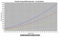
Kinetic energy SRM-Ergometer and flywheels
Transmission-Ratio of the SRM-Ergometer


The kinetic energy of the cyclist equals the rotational energy of the flywheels. The kinetic energy of the cyclist is: E = v² x m/2
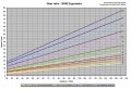
Please keep in mind that in a power-orientated test the change of regulation (hunting) increases linear to the fly mass-range in the single power steps. If one likes to have a change of regulation as little as it can be, it is best to ride in 3rd or 4th gear. It is also helpful to change to a smaller gear, when the no load-friction of the Ergometer in the 3rd or 4th gear is higher than the power at the beginning in an incremental stress test. In the 4th gear the no load-friction is about 80 watts with a cadence of 90, in the 1st gear it is about 50 watts. Therefore it is not possible to regulate less than 50 watts.
But please consider that the Rohloff gear box for regular performance diagnostics and step testing should be used in gear 8 or 9 (s. picture).
Notice
The default configuration for the most common Ergometer tests is installing the LARGE fly mass inside the gearbox on its own! Please remove the SMALL fly mass as described below! For more information on kinetic energy simulation, fly masses and gear ratio of the Rohloff hub see the manual or visit our webpage at www.srm.de
Change of the flyingwheels
Illustration with smaller flywheel and corresponding spacers
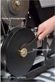
Removal and mounting instructions
The fly masses can easily be changed after taking off the left ergometer lid by loosening the brass-coloured counter-nut. Hand-tight fastening is enough. Always disconnect thee power supply from the Ergometer when opening the side covers! Never operate the Ergometer without the side covers! Before removing side covers insure fly masses have stopped spinning completely and use care when handling the fly masses to prevent injuries or bruises – both are very heavy!
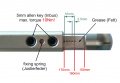
- To remove/mount a fly mass you need the following tools: One or two aluminum spacer, Torx screwdriver an nut wrench (Fig.1)
- Open the cap of the Ergometer by removing the seven Torx screws (marked red) with the Torx T30 wrench (Fig.2)
- Use the nut wrench to rotate the brass nut counterclockwise (Fig.3). Hold the fly mass to counter the tool pressure if needed
- Remove the nut and pull the two fly masses off thee axle (Fig.4). Pay attention not to damage the threads on the axle
- Replace the SMALL fly mass with one aluminum spacer (Fig.5) or add two spacers when replacing the LARGE fly mass. Make sure the groove :in the spacer coincides with the feather key in the axle
Always insure the correct fly mass/spacer configuration: When installing both fly masses always add the SMALL fly mass first onto the axle. When removing the SMALL fly mass, add one spacer first, then add the LARGE flywheel. Same when replacing the LARGE fly mass – add the SMALL fly mass first and then add the two spacers. When testing without any fly mass remove all parts including the brass nut.
- To reinstall the fly mass on the axle (Fig.6) make sure the groove in the fly mass coincides with the feather key in the axle. This :groove will lock the fly mass an prevent thee fly mass from spinning free
- Using the nut wrench, rotate the brass nut clockwise until hand-tight (Fig.7)
- Make sure the fly mass sits firmly, has no play on the axle and can rotate freely! Remove all tools inside the gearbox! Reinstall thee :cover with the seven Torx head screws. Do not over tighten!